
 VN
VNHow to use electrical wires and cables safely is a critical technical process that determines the success of every industrial electrical project, from low voltage power cable systems to medium voltage power cables. According to reports from the Fire Prevention, Fighting and Rescue Police Department (Ministry of Public Security), during the period from 2012-2020, 51.9% of electrical incidents could have been prevented simply by adhering to proper selection and safe installation procedures, as mentioned by evn.com.vn on July 8, 2024. This guide provides a comprehensive methodology from selecting materials according to Vietnamese standards (TCVN), safe installation techniques to professional acceptance testing procedures.
This article includes:
- How to calculate and select conductors according to power requirements
- Comparison of surface mounting and concealed installation methods
- Acceptance testing procedures according to TCVN 5639:1991
- Analysis of common mistakes and technical Q&A for M&E engineers and contractors
The content is designed to ensure absolute electrical safety for all electrical systems from workshops to large-scale industrial projects.
1. Phase 1: Selecting wires and cables according to proper technical standards
Selecting the right type of electrical wires and cables is the foundation of every safe electrical system. This decision not only affects operational efficiency but also directly relates to human safety and property protection. So how do we ensure how to use electrical wires and cables safely right from the selection stage?
1.1. Calculating and selecting conductor cross-section according to power requirements
Basic formula for calculating conductor cross-section:
Conductor cross-section: S = I / J
Where:
- S: Conductor cross-section (mm²)
- I: Current intensity (A)
- J: Allowable current density (A/mm²)
Current density table for copper and aluminum conductors:
| Conductor Type | Current Density (J) |
|---|---|
| Copper conductor | 6 A/mm² |
| Aluminum conductor | 4.5 A/mm² |
Current calculation for single-phase and three-phase systems:
- For single-phase systems: I = P / (U × cosφ)
- For three-phase systems: I = P / (√3 × U × cosφ)
Where cosφ is typically 0.8-0.9 for industrial equipment.
Practical example: A workshop with total power of 45kW, three-phase 380V power supply, cosφ = 0.85:
- Current: I = 45,000 / (1.732 × 380 × 0.85) = 80.4A
- With copper conductor having current density J = 6A/mm²
=> Conductor cross-section calculation: S = 80.4 / 6 = 13.4mm²
Therefore, selecting a copper conductor with 16mm² cross-section is appropriate.
1.2. Determining the power supply to use
Depending on each device, select the appropriate power supply:
Single-phase power supply (220V) is suitable for:
- Office equipment: computers, LED lights, air conditioners under 2HP
- Household appliances: refrigerators, washing machines, microwaves
- Maximum recommended power: 7-10kW
Three-phase power supply (380V) is used for:
- Industrial motors from 3HP and above
- Central air conditioning systems
- Production machinery, industrial welding equipment
- Elevators, cranes
1.3. Selecting conductors suitable for each application
1.3.1. Selecting cables according to structure and application
Depending on specific applications, select cables with appropriate structures:
- Single/flexible core wire (CV):
- Structure: 1 copper core + PVC insulation
- Application: Connecting household equipment such as switches, outlets, lighting.
- Double/multi-core cable (CVV):
- Structure: 2-5 copper cores + PVC insulation + PVC outer sheath
- Application: Used in transmission and distribution systems for large-scale projects or projects requiring high stability and durability.
- Fire-resistant cable (CXV):
- Structure: Copper core + XLPE insulation + fire-resistant PVC-Fr outer sheath
- Application: Emergency exits, fire protection systems, hospitals…
1.3.2. Selecting conductors according to installation environment
Below are recommended wire types for common installation environments:
| Installation environment | Recommended wire type | Technical Reason |
|---|---|---|
| Indoor, dry areas | CV | Economical, sufficient protection |
| Outdoor, wet areas | CXV, Underground cable | Waterproof, UV resistant |
| Fire protection areas | Fire-resistant CXV | Fire protection requirements per TCVN 3890:2023 |
| Industrial workshops | CVV or CXV | Impact resistant, electrical interference protection |
1.4. How to choose quality electrical cables
1.4.1. Quality inspection checklist for on-site wire inspection:
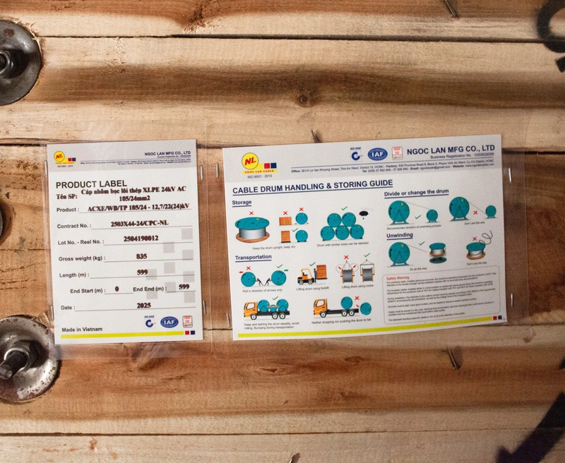
- Check labels and certifications:
- Clear brand logo (e.g: Ngoc Lan Cable)
- Complete information: wire type, cross-section, rated voltage. How to read and understand these technical specifications will help you accurately verify product quality.
- Quality standard labels issued by reputable quality inspection organizations such as IAF, JAS-ANZ…
- Production batch number and manufacturing year
- Physical inspection of conductors:
- Copper core: Natural red copper color, not discolored
- Flexibility: Bend 10 times without breaking or cracking
- Gloss: Insulation sheath is smooth and glossy, without cracks
- Diameter: Use calipers to check correct cross-section
- Check conductor resistance: According to TCVN 5935, maximum copper conductor resistance at 20°C:
- 1.5mm² wire: ≤ 12.1 Ω/km
- 2.5mm² wire: ≤ 7.41 Ω/km
- 4mm² wire: ≤ 4.61 Ω/km
- 6mm² wire: ≤ 3.08 Ω/km
1.4.2. TCVN standards for wires and cables:
| Standard | Scope of application | Main requirements |
|---|---|---|
| TCVN 7447 | Low voltage electrical installation systems | General regulations on installation, safety |
| TCVN 9207:2012 | Electrical conduit installation | Spacing, layout methods |
| TCVN 4086:1985 | Electrical safety in construction | General safety requirements |
| TCVN 9385:2012 | Lightning protection for buildings | Grounding systems, lightning protection |
To ensure quality and safe use of electrical wires, you should purchase from official authorized dealers like Ngoc Lan Cable and request warranty seals from the manufacturer.
2. Phase 2: Selecting safe and efficient installation methods
Selecting the appropriate installation method not only affects aesthetics but also determines the safety, maintenance costs, and system expandability of the electrical system. Each method has distinct advantages suitable for different types of projects.
After mastering the material selection principles in Phase 1, the next important step is determining the optimal installation method for the specific project.
2.1. Surface installation
Technical characteristics: Surface installation method involves arranging electrical wires and cables on wall surfaces, ceilings, or support structures such as cable ladders and metal conduits.
- Outstanding advantages:
- Easy inspection and maintenance: Can quickly detect faults and replace conductors without demolishing structures
- Low installation cost: Saves 30-40% cost compared to concealed installation
- High flexibility: Easy to add and adjust electrical circuits when expansion is needed
- Fast construction: Reduces construction time by 50% compared to concealed installation
- Limitations to note:
- Limited aesthetics, suitable for workshops and technical areas
- Requires better mechanical protection measures (conduits, cable trays)
- More susceptible to external environmental impacts
2.2. Concealed Installation
Technical characteristics: Concealed installation is the method of arranging electrical wires and cables inside building structures such as walls, floors, and ceilings through pre-installed conduits.
- Notable advantages:
- High aesthetics: Completely hidden, suitable for high-end residential and office buildings
- Optimal protection: Conductors are well protected from impacts, weather, and mechanical forces
- High safety: Reduces fire and explosion risks due to direct contact.
- Technical challenges:
- Investment cost 40-60% higher than surface installation
- Difficult repairs, requiring structural demolition
- Requires careful design from the initial stage, difficult to change later
2.3. Golden principles in installation to ensure safety
Mandatory safety rules to follow during installation:
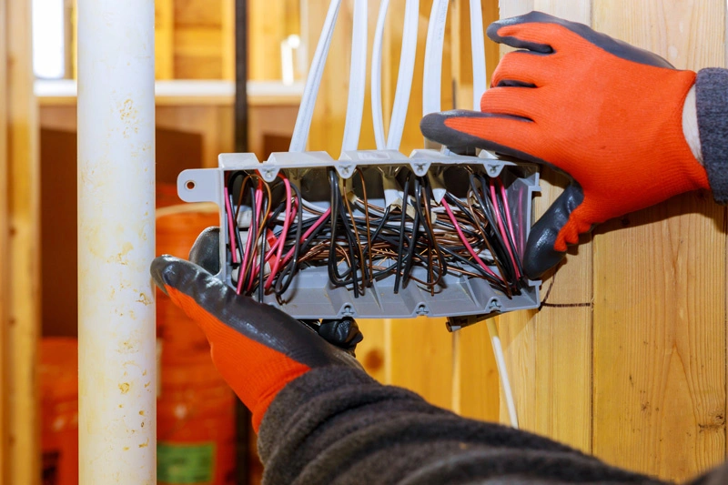
- Connection principles:
- Connections on double wires must be staggered
- Use dedicated junction boxes with protection temperature rating of IP54 or higher
- Mechanical protection measures:
- Use HDPE conduits for concealed routes
- Porcelain insulators or porcelain clamps at wall penetration points
- Cable ladders with covers for surface routes
After completing the selection of appropriate installation methods, the next equally important phase is ensuring compliance with acceptance testing procedures to confirm the quality and safety of the entire system.
3. Phase 3: Acceptance testing and handover of electrical systems
Acceptance testing is the final but extremely important phase that determines the quality and safety of the entire electrical system. A rigorous acceptance testing process helps detect potential faults early, prevents serious incidents during operation, and ensures how to use electrical wires and cables safely throughout the project lifecycle.
3.1. Electrical system acceptance testing procedures according to regulations
3.1.1. Preparation of acceptance documentation
According to TCVN 5639:1991, acceptance documentation must include:
- Design documentation:
- Approved design drawings
- Technical specifications and estimates
- Approval documents from competent authorities
- Construction documentation:
- As-built drawings
- Construction diary with complete supervisory signatures
- Acceptance reports for each construction phase
- Equipment and material records used
- Quality certification documentation:
- Equipment origin certificates
- Test reports from accredited laboratories
- Training certificates for construction workers
3.1.2. Static Testing
Quality inspection of installation without power supply:
- Mechanical inspection:
- Firmness of connections
- Safe distances between conductors
- Condition of insulation and cable sheaths
- Insulation resistance measurement:
- Use Megger 500V DC meter
- Standard: ≥ 0.5 MΩ for low voltage circuits
- Check between phases and between phase and ground
- Grounding system inspection:
- Measure grounding resistance using specialized meters
- Standard: ≤ 4Ω for electrical systems using 380/220V voltage level, ≤ 10Ω for cases with power consumption under 100kVA.
3.1.3. No-load Testing
This is when we check the electrical system operation without actual load. The main purposes are:
- Verify correct connections: Ensure the entire system from power supply, electrical panels, lines, to equipment are all connected according to design schematics.
- Check continuity and insulation: Ensure no short circuits, open circuits, or electrical leakage that could cause danger.
- Detect preliminary faults: Any strange noises, burning smells, or unusual incidents must be detected and handled immediately.
- Measure basic parameters (if applicable): Although standards don't specify clearly, experts will still monitor parameters such as voltage, no-load current (if applicable to specific equipment), and system stability.
**Note: Each electrical project will have specific designs. You need consultation from professional electrical engineering teams to conduct the safest inspections.
3.1.4. Load Testing
- Check and eliminate equipment issues that could cause incidents during load operation
- Readjust appropriate production technical parameters to prepare for commissioning
3.2. Checklist of 9 critical errors to check before handover
Post-installation inspection is an extremely important phase to detect abnormalities such as:
- Inappropriate circuit breakers: Breaking current too large compared to wire load capacity
- Missing ELCB: Not installing residual current devices for outlet circuits
- Loose connections: Use thermal guns to detect abnormal hot spots
- Mixed wire types: Connecting copper-aluminum without specialized connectors
- Inadequate grounding system: Grounding resistance > 4Ω and metal equipment housings not grounded
- Poor insulation: Insulation resistance < 0.5MΩ
- Faulty conductors: Cable sheath cracked, copper core broken strands
- Non-compliance with distances: Violating TCVN regulations on safe distances
- Missing safety signs: Not installing high voltage warning signs, danger alerts
Successfully completing acceptance testing ensures how to use electrical wires and cables safely throughout the operation period. However, to maintain long-term effectiveness, it's necessary to avoid common mistakes during construction and operation.
4. Common mistakes when using electrical wires and cables unsafely
Mistakes in electrical construction not only waste budget but also pose potential threats to human safety. Understanding common errors helps engineers and contractors proactively prevent and apply proper safe electrical wire usage standards.
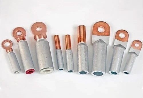
4.1. Most critical mistake: Careless connections
Technical consequences: When connecting copper wire with aluminum wire without using connecting terminals, over time the aluminum wire will corrode, leading to poor contact, causing overheating and fire explosions.
Real case: In an electrical repair case at a residential home, the electrician discovered the cause of the electrical fault was due to directly connecting copper and aluminum wires together without using connecting tools.
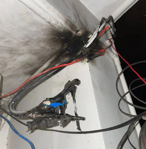
Solution: Use copper-aluminum connecting terminals or electrical wire connectors (cable connectors, cable clamps) to connect two electrical conductors of different materials like copper and aluminum. It's best to have electricians or qualified personnel perform this to ensure safety, absolutely do not attempt connections or repairs without knowledge of electrical wire installation, as this can easily lead to unfortunate incidents.
4.2. Using electrical wires beyond service life
Statistics from the Fire Prevention, Fighting and Rescue Police Department (Ministry of Public Security) show that from 2015 to 2019, fires caused by electrical system and equipment failures reached over 8,100 cases (accounting for 45.3%). Particularly, electrical wires used for many years gradually become old, insulation sheaths age, combined with people's poor understanding of electrical safety, leading to serious fire and explosion incidents.
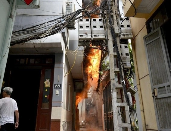
Solution: Regularly inspect electrical wire quality, perform periodic maintenance to timely detect issues that may pose fire and explosion risks.
4.3. Ignoring grounding systems – A serious mistake
Lack of grounding systems causes metal equipment housings to become electrically charged when insulation faults occur. Induced voltage can reach up to 220V, causing electric shock leading to tragic consequences.
5. Frequently asked questions from engineers and contractors about electrical safety
The following questions are compiled from practical experience of electrical power experts, helping you quickly resolve the most common technical concerns during design and construction processes.
5.1. Is it mandatory to ground all electrical equipment in workshops?
Yes, this is mandatory according to TCVN 4086:1985. All equipment with metal housings must be connected to protective grounding to ensure human safety.
Technical reason: When insulation faults occur, electrical current will be conducted to ground instead of accumulating on equipment housings, preventing electric shock risks.
5.2. Is it necessary to use fire-resistant cables for the entire electrical system?
Not entirely necessary for all circuits. According to TCVN 6306, fire-resistant cables are only mandatory for:
- Fire protection and fire alarm systems
- Emergency exits and emergency lighting
- Critical control circuits in high-rise buildings
For ordinary circuits, CVV or CXV cables are sufficient to meet standard requirements for safe electrical wire and cable usage.
5.3. Aluminum core vs. copper core conductors - which is more cost-effective for main trunk lines?
Comparative evaluation through detailed criteria in the table below:
| Criteria | Aluminum Wire | Copper Wire |
|---|---|---|
| Initial cost | 30-40% lower | Higher |
| Electrical conductivity | About 61% compared to copper | 100% (reference comparison figure) |
| Weight | Only 30% as heavy as copper | Heavier |
| Service life | 25-30 years | 40-50 years |
| Maintenance | Check every 3-6 months | Check every 6-12 months |
Recommendation: For main trunk lines with large distances (> 100m), aluminum conductors provide significant cost savings. However, cross-section must be increased 1.6 times compared to copper conductors to ensure equivalent current carrying capacity.
5.4. Comparing efficiency between surface and concealed installation for workshops?
For workshop environments, surface installation is more efficient in terms of:
- Cost: Saves 40-60% compared to concealed installation
- Maintenance: Easy inspection and repair
- Expansion: Flexible addition of new circuits when needed
However, additional investment is required for mechanical protection systems such as cable ladders and metal conduits.
5.5. What types of electrical cables are permitted for direct underground burial?
According to TCVN 9207:2012, some types of armoured cables are permitted for underground burial such as:
- CVV/DSTA – 0.6/1kV Cable: Low voltage cable with 2 steel tape armour layers
- CXV/DATA – 0.6/1kV Cable: Low voltage cable with 2 aluminum tape armour layers
- NYY Cable: European standard with PE sheath
Important note: If construction is at sites with many obstacles and uneven terrain, direct burial is not permitted but must be placed in HDPE protective conduits or concrete troughs to protect cables from folding or bending on various terrains.
5.6. How to choose cable suppliers with export experience and reputation?
When selecting suppliers for important projects, you should evaluate according to the following criteria:
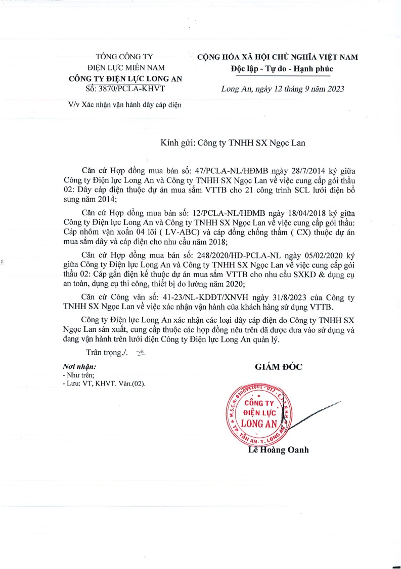
- Certifications and practical experience:
- Successful operation confirmation (successful grid connection): This is confirmation that products have been recognized by EVN and operated successfully on the electrical grid for 2-5 years without quality incidents.
- Export experience: Ability to meet strict international standards (IEC, AS/NZS)
- Operating time: Minimum 10-15 years to ensure capability and reputation.
- Technical capability:
- High voltage electrical laboratory meeting standards
- Engineering team with university/college degrees in electrical specialization
- In-depth technical consulting capability
Practical example: Ngoc Lan Cable with over 30 years of experience has successfully exported to many countries, especially the Australian market with very strict AS/NZS standards. This proves the ability to meet the highest technical requirements in the industry.
Quick evaluation criteria:
- Have complete Certificate of Origin and CO (Certificate of Origin)
- Provide test reports from independent laboratories
5.7. What does periodic inspection procedures for workshop electrical systems include?
A periodic electrical system inspection procedure is typically performed following these steps:
Step 1: Preparation and Initial Assessment
- Collect technical documents, electrical system diagrams, maintenance history.
- Develop inspection plan, determine scope and necessary tools.
- Notify inspection schedule to relevant parties for coordination.
Step 2: Visual and Physical Inspection
- Check condition of conductors, electrical cables, electrical panels, equipment for signs of damage, burning, oxidation or looseness.
- Ensure connections are secure, no signs of corrosion or mechanical damage.
Step 3: Inspection Using Specialized Measuring Instruments
- Measure voltage, current, resistance using multimeters.
- Measure insulation resistance using Megger meters to detect electrical leakage.
- Use thermal cameras (Thermal Imager) to detect hot spots, connections with abnormal temperatures.
- Check load distribution, ensure no overload or phase imbalance phenomena.
Step 4: Check Grounding and Earthing Systems
- Measure grounding resistance, check grounding rods, grounding wires to ensure safety and compliance with standards.
Step 5: Check Protection Equipment
- Check operation of circuit breakers, switches, ELCB (RCCB), protection relays.
- Ensure protection equipment operates accurately and timely when faults occur.
Step 6: Load Testing and Trial Operation
- Monitor system operation under actual load, check operating parameters.
- Evaluate stability and efficiency of electrical system under working conditions.
Step 7: Cleaning and Maintenance
- Clean electrical panels, equipment, remove dust and insects affecting operation.
- Tighten connections, replace damaged components if necessary.
Step 8: Prepare Inspection Report
- Record inspection results, discovered issues and propose corrective measures.
- Submit report to management or investors for monitoring and continued maintenance.
Step 9 – Final: Develop Next Periodic Maintenance Pla
- Based on inspection results, build maintenance and periodic inspection schedule suitable for system condition.
Strict adherence to this inspection procedure not only ensures how to use electrical wires and cables safely but also helps detect potential issues early, reducing repair costs and unexpected downtime.
6. Conclusion
After completing this guide, you have mastered the complete process of how to use electrical wires and cables safely:
- Calculate wire cross-section accurately and appropriately for each type of equipment
- Distinguish and select the right wire type according to environment and specific application
- Apply surface or concealed installation methods based on aesthetic requirements and budget
- Implement 4 acceptance testing phases according to TCVN 5639:1991 from document preparation to load testing
- Avoid 9 serious mistakes such as loose connections, lack of grounding, incorrect wire cross-section selection
- Perform periodic inspections according to monthly, quarterly, annual cycles with specific safety standards
To ensure optimal quality, choose electrical cables from Ngoc Lan Cable – a reputable manufacturer with 30+ years of experience and national grid connection certification.

