
 VN
VNIn solar power systems, the weak point that can cause catastrophic fire and explosion does not lie in the panel itself. The danger lies at the contact points. Traditional junction boxes easily leak DC current because their design is not waterproof. This is why MC4 connectors were developed to solve this risk under harsh environments. These environments include continuous UV radiation, high humidity, and large temperature fluctuations.
This article provides a comprehensive guide on MC4 connectors. It helps readers understand everything from structure to practical applications in solar power systems.
- Structure and safety materials – Detailed analysis of 3 core components of MC4, combined with fire-resistant material standards to ensure durability and safe operation
- Connector classification – Comparison of popular connector types including standard type, Y-branch, and fuse-integrated type for different usage needs
- Practical applications – Deployment capability from residential rooftop systems to large-scale solar farms in various environmental conditions
Additionally, Ngoc Lan Cable provides standard technical installation instructions with a 4-step crimping process. This helps engineers easily apply it in practice. Proper installation is the key factor that determines the safety and operating efficiency of the entire solar power system.
1. What are MC4 connectors? Structure and safety materials
MC4 connectors are specialized electrical connectors. They connect conductors of solar panels (solar power systems) with each other or with other equipment in PV systems.
“MC4” comes from “Multi‑Contact 4 mm”. MC is the name of the manufacturer Multi‑Contact (now part of Stäubli Electrical Connector). The “4” indicates the contact pin diameter of approximately 4 mm.
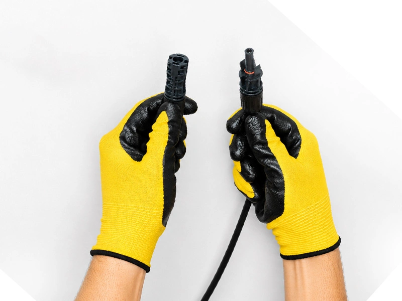
MC4 connectors consist of 2 parts: male plug and female socket. They have a locking mechanism, so once plugged in, they will not come loose due to cable vibration or pulling.
The materials that make up the connector are specially designed. Each component meets a specific technical requirement:
- The protective housing is made from PPO/PA insulation material. It has high heat resistance, UV protection, and limits cracking when used outdoors. The UL94-V0 fire resistance standard helps the housing self-extinguish quickly. This reduces the risk of fire spreading to nearby modules.
- The tinned copper alloy core maintains low contact resistance. It effectively prevents oxidation after many connections. As a result, current transmission is stable, heat generation is limited, and energy loss is reduced.
- The positive locking mechanism keeps the connection secure. It prevents cable loosening due to vibration or pulling force. The locking jaw only opens with a specialized tool. This meets the NEC Article 690.33 safety standard and limits unintended circuit disconnection incidents.
2. Common types of MC4 connectors
Based on technical function and application cases, MC4 is divided into 3 main variants. These variants are popular in solar energy projects.
Standard connector (Standard MC4) – Direct connection between module and inverter
The standard type consists of one male connector and one female connector. They are crimped tightly to the DC cable. This simple structure is suitable for direct connection between two panel modules. It also connects the final string to the inverter. Therefore, current flows in one clear direction, making it easy to control and maintain.
Y-branch connector – Parallel connection of multiple panel strings
Popular in parallel connection is the specialized Y-branch connector. The MC4 Y-connector design with 2 inputs and 1 output allows combining current from two panel strings. This does not change the total voltage. As a result, output power doubles while maintaining the rated voltage level suitable for the inverter.
Inline fuse connector – Automatic protection against overload
The fuse-integrated variant is installed directly on the wire. It protects the system from overcurrent and short circuits without needing a separate combiner box. When current exceeds the allowed threshold, the fuse automatically disconnects to protect the string. Therefore, this solution reduces equipment costs and simplifies maintenance for small-scale solar power systems.
3. Practical applications of MC4 connectors
Different system scales lead to different technical requirements for voltage, current, and environmental durability. Therefore, the applicability of MC4 connectors must be evaluated specifically for each installation environment.
Residential rooftop systems
In small-scale solar power systems, MC4 connectors link multiple modules into one string before connecting to the inverter. The string voltage is usually within the safe limits of the standard connector. Therefore, engineers do not need to add many isolation devices. This helps the design to be more compact and saves installation costs.
Large-scale solar farms
At solar farm construction sites, choosing the right MC4-compatible cable cross-section standard directly determines transmission efficiency. MC4 connectors support many different cable cross-sections. This allows engineers to balance between material costs and current loss. Therefore, this solution is flexibly applied to both short and long wire runs in large-scale projects.
Harsh environments (coastal areas, deserts)
In coastal projects or high-humidity environments, MC4 connectors meet IP67/IP68 waterproof standards. This prevents water and salt vapor from entering and limits copper core corrosion. The EPDM rubber gasket creates stable tightness. This helps the connector operate durably even in harsh weather conditions.
4. 4-step crimping process guide and DC arcing risk
Understanding how to properly connect MC4 connectors is a mandatory skill to prevent inverter fire and explosion risks.
Step 1: Strip the cable accurately using specialized wire strippers
Use cable strippers to remove the insulation layer with the correct standard length. Avoid scratching the copper core. Stripping too short will reduce the contact area and easily cause heat generation. Stripping too long exposes metal and increases the risk of short circuit. Therefore, you must strictly follow the manufacturer's instructions.
Step 2: Crimp the copper core tightly using crimping pliers
Use specialized crimping pliers to press the copper core tightly into the MC4 metal connector. This creates a secure connection and reduces contact resistance. Appropriate crimping force helps transmit electricity stably. It limits heat generation without breaking the copper strands inside.
Step 3: Check the firmness by pull testing
After crimping, you need to pull a test to check the connection firmness. If the copper core comes loose from the crimp terminal, re-crimp with appropriate force or replace with a new crimp terminal. The old terminal may have been deformed.
Step 4: Complete assembly and lock using positive locking
Push the male connector into the female connector until you hear a clear “click” sound. This confirms the locking jaw has completely closed. When maintenance disassembly is needed, you must disconnect the DC circuit breaker first. Then only remove using a specialized MC4 unlocking wrench.
At the same time, engineers need to understand how to check MC4 connectors for looseness or burning by visually observing unusual signs. Black marks, plastic housing deformation, or burning smell are serious warnings requiring immediate replacement. Regular inspection using resistance measuring equipment helps detect problems early before incidents occur.
Understanding the correct way to connect MC4 solar connectors is an important factor to avoid inverter fire and explosion risks. Never disconnect the connector when the system is under load. This can create DC arcing that is extremely hot and difficult to self-extinguish.
⚠️ Safety warning – DC arcing
When disconnecting a high-voltage DC circuit, air becomes ionized and creates continuous conducting plasma arcing. The arc temperature is extremely high. It can melt metal and cause fire in just a few seconds.
Unlike AC arcing which self-extinguishes at the zero-crossing point, DC arcing continues continuously. Therefore, the risk of fire and explosion is much greater. For this reason, all removal and installation operations must be performed after the power source has been completely disconnected.
5. Frequently asked questions (FAQs)
5.1. How long is the lifespan of MC4 connectors under actual operating conditions?
The actual lifespan depends on the number of connection cycles. Each removal and installation wears down the tin plating layer. Additionally, UV intensity at the site and daily temperature fluctuations also directly affect material lifespan.
5.2. Will touching MC4 connectors cause electric shock?
No. MC4 connectors have a touch-safe design. The metal part inside is covered by PPO/PA insulation housing. This limits the risk of direct electrical contact. Even when not fully locked, the metal core remains deep inside the protective housing. However, to ensure safety, you should still disconnect the power before handling.
5.3. Are MC4 compatible with connectors from other manufacturers?
In theory, MC4 connectors can be compatible between many brands. However, small differences in locking jaw dimensions can make the connection loose. This increases heat generation and reduces lifespan. Therefore, you should use male and female connectors from the same brand. Ideally from the same production batch.
6. Choosing synchronized MC4 and DC cables for PV systems
Standard MC4 connectors are a protective solution for safe energy systems. They prevent fire incidents and dangerous DC arcing. Therefore, the system maximizes its design performance throughout the project lifecycle.
Main content presented in this article:
- MC4 structure with 3 main components (fire-resistant PPO/PA housing, tinned copper core, positive locking) and the role of each component in ensuring safety.
- Classification with 3 main variants – Standard connector, Y-branch, and fuse-integrated.
- Practical applications from small-scale residential rooftop systems to large-scale solar farms and harsh coastal environments.
- Installation process with 4 accurate crimping steps (stripping, crimping, checking, assembling) and important warnings about DC arcing.
Contact Ngoc Lan Cable immediately for expert answers to your questions. Get consultation on choosing the most suitable electrical cable solutions for each project.

