VN
VN
- Physical characteristics of specialized PV cables: XLPO insulation structure, tinned copper conductor, and EN 50618, IEC 62930, TCVN 13209 standards
- Optimized electrical circuit configuration: Series vs. parallel connection comparison, analysis of voltage impact on system performance and MPPT efficiency
- Standard 8-step installation process: From site survey, mounting rack installation, DC/AC wiring, grounding to official operation
The article also summarizes practical problem-solving experience from actual installation sites. This helps contractors proactively prevent errors, maintain construction progress and meet the strictest acceptance requirements.
1. Physical characteristics and standards for solar cables
Specialized solar cables differ from residential wires due to their design for harsh outdoor environments. They withstand high UV radiation and large thermal fluctuations. The XLPO/XLPE insulation layer prevents cracking, increases durability and ensures stable operation.
According to EN 50618, IEC 62930 and TCVN 13209 standards, cables must meet mechanical strength requirements. They must resist fire spread and ensure technical safety. This makes project acceptance more favorable.
The tinned copper conductor increases oxidation resistance. It maintains stable contact resistance in humid environments and high temperatures. Meanwhile, the XLPO halogen-free (LSZH) outer sheath reduces toxic gas during fires. This makes it suitable for rooftop solar systems and industrial zones.
2. Choosing electrical circuit configuration: Series and parallel connection
The choice between series or parallel solar panel connection depends on the MPPT inverter voltage range and system design.
Series connection increases string voltage. This helps reduce cable cross-section and transmission losses. However, this configuration is sensitive to shading. Just one degraded panel can affect the entire string.
Parallel connection increases total current. This requires larger DC cable cross-sections to handle thermal load. In return, strings operate more independently. This reduces mismatch effects or local faults.
Series-parallel hybrid configuration is commonly used in large PV systems. It balances voltage and current to optimize maximum power point (MPP). Panels are connected in series to form strings. Then multiple strings connect in parallel through a combiner box to increase total system efficiency.
3. Construction process and solar panel cable installation
The 8-step construction process from survey to operation is the foundation for project efficiency and safety. Even one small error can cause power loss. Coordination between M&E contractors, design engineers and inspection teams is very important.
Step 1: Site assessment and string design
Site survey for roof or ground layout includes measuring tilt angle, azimuth direction and evaluating shade impact from surrounding structures. This data is entered into simulation software like PVsyst or HelioScope. This optimizes panel string configuration and reduces voltage drop along transmission lines.
Step 2: Mounting system installation and panel fixing
The anodized aluminum rail system is installed at the correct design tilt angle. Rows must be parallel and uniform. Each fixing point uses stainless steel bolts combined with EPDM waterproof washers. Bolts must be tightened to proper torque according to manufacturer guidelines. This ensures firmness. During rooftop construction, occupational safety requirements must be strictly followed.
Step 3: DC wiring and MC4 connector connection
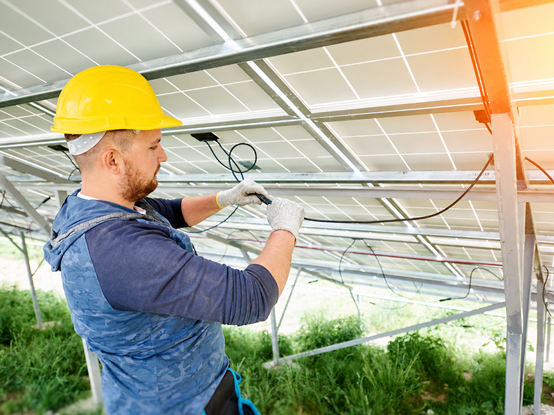
Connect panels using specialized PV cables and MC4 waterproof connectors rated IP67. This ensures safe outdoor connection. Crimp terminals properly to minimize loose contact and prevent arc flash.
Calculate appropriate DC cable length to avoid cable tension. Fix cables to rails using UV-resistant tie-wraps. This reduces vibration and protects the insulation layer.
Step 4: DC isolator and combiner box installation
The DC isolator and combiner box integrate fuses or circuit breakers for overcurrent protection. They automatically disconnect the circuit during faults. This reduces cable fire risk. Combiner boxes are typically installed near panel arrays. They avoid direct rain exposure and meet minimum IP65 waterproof rating.
Wire from strings into the combiner box following clear polarity rules. Positive and negative busbars are completely separated. Each connection point is clearly labeled with string number and polarity.
Step 5: Inverter installation and configuration
Install the inverter in a well-ventilated location. Avoid direct sunlight and ensure heat dissipation distance according to manufacturer recommendations. Mount the equipment on a sturdy rack to ensure safe operation.
Configure MPPT parameters like Voc voltage, Isc current and number of panel strings accurately through screen or monitoring software. The inverter then automatically tracks maximum power point (MPP) to optimize electrical output from the panel array.
Step 6: AC wiring and electrical panel connection
Power from the inverter is fed into the electrical panel using multi-core AC cables. This combines full protective equipment like isolating switch, SPD surge arrestor and RCD residual current device to ensure system safety. SPD connections to ground must be short and technically correct to increase protection efficiency. The inverter must meet grid synchronization requirements according to IEEE 1547 or VDE-AR-N 4105 standards. Voltage and frequency must remain within permitted limits.
Step 7: Grounding and equipotential bonding
The panel frame and rail system must be equipotentially bonded. Ground them using appropriate copper wire to prevent electric shock and safely conduct leakage current. Grounding points must be firmly fixed, loosening-resistant and synchronized across the entire system.
Step 8: Testing and official operation
Check grounding wire continuity using low-resistance measurement equipment. This ensures resistance from all metal points to ground stake meets standards. This reduces electric shock risk when touching the mounting frame. Test DC circuits for withstand voltage according to IEC 60364-6 standard. Only certified electrical safety technicians should perform this. Before energizing, complete final checks including tightening electrical bolts, confirming correct polarity at connection points and ensuring no exposed conductors.
4. Frequently asked questions (FAQ)
4.1. Is PVC conduit protection mandatory for all outdoor DC cable runs?
Whether conduit is needed depends on actual installation conditions. If cables run underground or in areas with high mechanical impact risk, conduit is a necessary solution. It protects cable sheath from rodents, tree roots or external impacts. Conversely, for cables installed on steel racks and fixed with properly spaced clamps, protective conduit may not be mandatory.
4.2. What is the minimum cable cross-section for DC strings when distance is long?
Distance from panel array to inverter directly affects voltage drop. Cable cross-section must be calculated based on both current carrying capacity and permissible voltage drop. Many contractors make the mistake of calculating based only on current carrying capacity. They ignore voltage drop factor. This leads to significant energy loss during long-term operation.
5. Choosing solar cable solutions meeting technical standards
Solar panel cable installation meeting technical standards is the foundation for a sustainable renewable energy project. Selecting cable manufacturers with international certification is an important factor to ensure system reliability.
Main knowledge from this article includes:
- Physical characteristics of PV cables: XLPO insulation withstands extreme temperatures, tinned copper conductor resists oxidation, complies with EN 50618, IEC 62930 and TCVN 13209
- Electrical circuit configuration: Series connection increases voltage, parallel connection increases current and resists shading
- Standard 8-step process: From site survey to operational testing following technical standards
For technical solution consultation needs, please contact Ngoc Lan Cable for professional support from our experienced engineering team.