
 VN
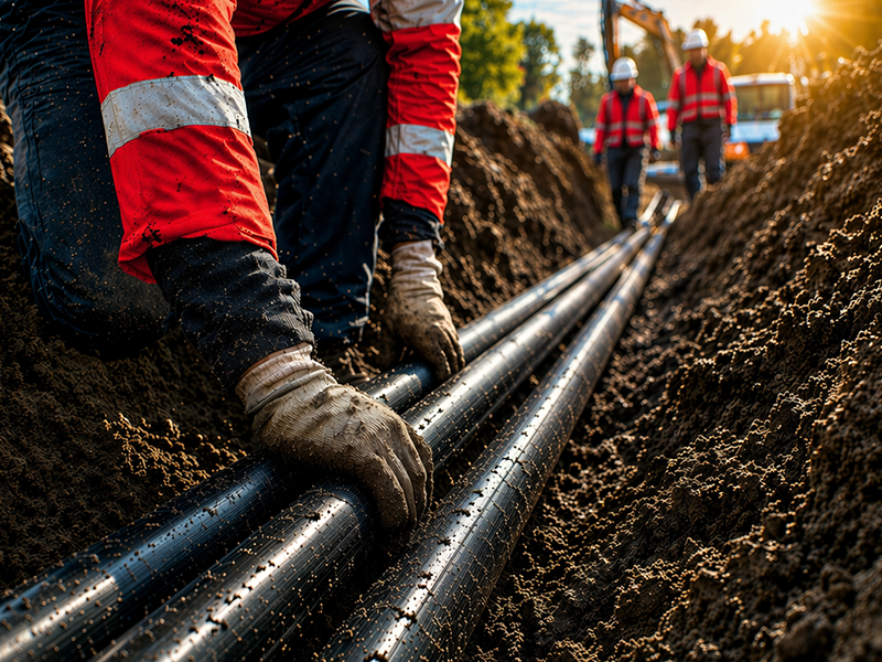
VNThe activity of installing electrical conduit underground in large-scale industrial projects requires very high technical precision. International electrical contractors deploying FDI projects in Asia must follow strict standards. Underground cable systems must comply with NEC 300.5 (minimum burial depth requirements) and IEC 61386-24 (conduit mechanical strength requirements).
This article provides a comprehensive construction design guide for field engineers. It includes:
- International standards foundation (NEC/IEC): Explains core mandatory requirements for underground electrical systems.
- Burial depth: Detailed reference table for each conduit type (RMC, PVC, direct burial). We provide both inch and mm units.
- 5-step construction process: From trench excavation, conduit installation, cable pulling, backfilling to final acceptance. We include specific technical parameters.
Ngoc Lan Cable presents a clear 5-step construction process. Each step has mandatory technical specifications in both inches and millimeters. This helps engineering teams apply the standards easily.
1. International standards: NEC Article 300.5 and IEC 61386-24
The design of underground conduit systems worldwide relies on 2 core standards. These standards serve as mandatory foundations for medium and large-scale electrical projects. They are especially important in heavy industrial zones and thermal power plants.
NEC 300.5 standard specifies minimum burial depth to protect systems from mechanical impact from the surface. The depth is measured from the top of the conduit to the finished grade. The depth varies depending on the material. For example, rigid metal conduits like RMC/IMC only need about 150 mm (6 inches). PVC Schedule 40 conduits need up to 450 mm (18 inches). Areas with vehicle traffic or heavy loads need an additional 150 mm for safety.
IEC 61386-24 standard requires conduits to meet compression strength ratings such as 450N or 750N. These ratings show the ability to resist deformation when the conduit bears loads from soil, vehicles or external pressure. The 450N rating suits normal installation conditions. The 750N rating is used in areas with high mechanical loads. These areas include container yards, industrial warehouses or places where forklifts operate frequently.
In practice, engineers start by determining burial depth according to NEC 300.5 based on the conduit type used. Then they check additional strength requirements according to IEC 61386-24. This “2-layer” checking method ensures the system has both safe depth and good impact resistance. This minimizes risks during construction and operation.
2. Cable burial depth compliance according to NEC 300.5
Burial depth is one of the most strictly controlled parameters during underground electrical system acceptance testing. This parameter affects not only the load-bearing capacity from the ground surface. It also ensures safety for excavation and maintenance activities later.
For metal conduits like RMC (Rigid metal conduit) and IMC (Intermediate metal conduit), the minimum burial depth is only about 150 mm (6 inches). Thanks to high-rigidity materials like galvanized steel or aluminum alloy, these conduit types resist force very well. They can withstand pressure from trucks or construction equipment. However, RMC/IMC costs are usually 40-60% higher than plastic conduits. Installation costs are also higher. Therefore, engineers only use them in areas requiring high mechanical protection.
In contrast, PVC conduits (Schedule 40 and Schedule 80) need a burial depth of about 450 mm (18 inches). Due to lower force resistance than metal, burying deeper helps reduce the risk of deformation or cracking under vehicle loads or construction activities. Although Schedule 80 has walls about 30% thicker and resists impact better than Schedule 40, NEC regulations require both types to follow the same burial depth level.
Especially in areas with vehicle traffic, all conduit types must be buried deeper. The additional depth depends on the conduit type, cable type, and specific installation conditions.
| Conduit type | Minimum depth (Normal conditions) |
|---|---|
| RMC / IMC (rigid metal) | 6 inches (150 mm) |
| Schedule 40 PVC | 18 inches (450 mm) |
| Schedule 80 PVC | 18 inches (450 mm) |
| Direct burial cable (no conduit) | 24 inches (600 mm) |
Based on these precise design parameters, field engineers can mark the route and begin the physical construction process.
3. 5-Step process for installing electrical conduit underground
Construction in actual practice needs strict control at each step. The process must follow correct standards to avoid errors that can affect the entire system lifespan.
3.1. Trenching and bedding
The trench needs a minimum width of 2 times the conduit diameter plus 12 inches (300 mm) on each side. This ensures enough space for construction and compaction. For example, with a 4-inch (100 mm) diameter PVC conduit, the minimum trench width must reach 32 inches (800 mm).
Technically, the trench bottom must have a layer of fine sand or crushed gravel with 4 inches (100 mm) thickness as a protective bedding layer. This helps distribute loads and prevents uneven settling. The sand used must be clean, with grain size from 2-5 mm. It must not contain large stones or broken brick pieces that can puncture plastic conduits.
After that, check the trench slope at about 0.5% – 1% for good drainage. This limits water accumulation that affects cables.
3.2. Conduit installation and expansion joints
PVC conduits can be joined using solvent cement or mechanical couplings. Cement creates a bond as strong as a single-piece conduit but needs about 15 minutes to dry. Mechanical couplings use rubber O-rings. They install faster and handle thermal expansion better.
According to standards, place an expansion joint every 200 feet (about 60 m) or at turns over 30°. This joint allows the conduit to expand/contract about 2-3 inches (50-75 mm) when temperature changes. This prevents cracking or joint separation. In areas with large temperature fluctuations, reduce this distance to 150 feet (45 m) per joint.
After installation, check the straightness of the conduit line. The deviation should not exceed 1 inch (25 mm) per 10 feet (3 m). This prevents water accumulation or difficulty when pulling cables later.
3.3. Fishing wire and cable pulling
The fishing wire technique through underground systems needs specialized cable pulling lubricant instead of petroleum grease. This avoids corroding the cable sheath. Lubrication significantly reduces friction and protects the cable sheath during pulling in the conduit.
More importantly, the cable pulling force must be strictly controlled. Do not exceed 80% of the manufacturer's limit. If you pull too much, the cable can have damaged conductors or deformed insulation. This leads to failures later.
When passing through bends, ensure bending radius ≥ 12 times cable diameter to avoid kinking. At turning points, use guide rollers to reduce friction and keep cables in the correct position.
3.4. Backfilling and compaction
The first backfill layer about 6 inches (150 mm) thick must be fine sand or clean soil without stones. Spread and compact this layer gently by hand to avoid displacing the conduit. Then continue backfilling in layers 8-12 inches (200-300 mm) thick. Each layer must be compacted to achieve about 85% standard density.
According to regulations, at 12 inches (300 mm) depth from the conduit top, place a warning tape (red or orange color). This warns of cables when digging later. Some tapes also have a metallic core for easy detection with locating equipment.
The compaction process must be checked using specialized equipment to ensure it meets requirements. If the density is insufficient, the soil can settle and damage the surface above.
3.5. Acceptance testing and as-built documentation
After backfilling, check the insulation resistance of the cable using a Megger (500V or 1000V DC). The minimum value is usually ≥ 1 MΩ/km (low voltage) and ≥ 10 MΩ/km (medium voltage) to ensure no damage. If results are abnormal, use TDR to locate the fault.
The as-built drawing must show the exact positions of manholes, joints, expansion joints and crossing points. It usually includes GPS coordinates. Store this data in the GIS system for maintenance purposes. This helps locate cables quickly when repairs or expansion are needed later.
5. Investing in standards is investing in sustainability
Understanding and applying the NEC/IEC code to underground cable systems creates a solid foundation protecting industrial project lifecycle. Compliance with technical specifications not only reduces incident risks but also saves maintenance costs. It ensures safe long-term operation.
This article provided:
- Standards foundation: Clarifies NEC 300.5 (burial depth) and IEC 61386-24 (mechanical strength) to determine correct technical requirements.
- Design specifications: Guides burial depth for each conduit and cable type with inch/mm units.
- Construction process: 5 steps from trench excavation, conduit installation, cable pulling, backfilling to acceptance testing according to standards.
- Practical solutions: Compares direct burial and conduit methods. Includes safe clearance regulations with other underground infrastructure.
The engineering team at Ngoc Lan Cable is ready to provide in-depth technical consulting. We answer all questions about underground cable solutions for your project.

