
 VN
VN- The basic definition of cable voltage rating and the Uo/U(Um) symbol structure
- Safe rating selection principles based on grounding systems
- The role of insulation materials (PVC, XLPE) in temperature limits
- Testing requirements and IEC 60502 compliance
Ngoc Lan Cable decodes the voltage symbol structure in the article below.
1. What is cable voltage rating? Decoding the Uo/U(Um) symbol
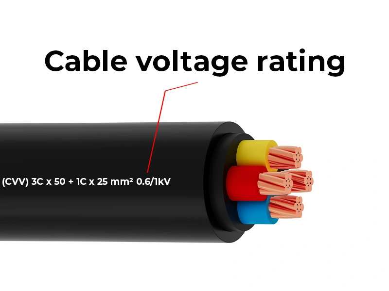
Cable voltage rating is the maximum voltage that a cable's insulation can safely and continuously handle during operation. This parameter is the basis for selecting cables that match the system's working voltage. Technical datasheets show the voltage rating using the standard symbol U₀/U(Um).
Decoding the Uo/U(Um) symbol:
- Uo — Phase-to-earth voltage: U₀ is the root mean square (RMS) voltage between one conductor core and earth in a three-phase electrical system. This parameter determines the cable insulation thickness. It protects against electrical failure between the conductor core and the outer metallic sheath.
- U — Phase-to-phase voltage: U is the RMS voltage between any two conductor cores in the cable. In a balanced three-phase system, this value is approximately 1.73 times (√3) higher than U₀. U defines the insulation capacity between conductor cores.
- Um — Maximum system Voltage: Um is the maximum RMS voltage that the cable is designed to withstand under temporary overvoltage conditions. Um is typically 10–20% higher than U to account for short-term overvoltages. The cable must withstand Um without insulation breakdown.
Understanding these voltage symbols is an essential first step. This knowledge supports safe electrical network design. Engineers can then select cables that match each type of grounding system.
2. Selecting the right voltage rating in design
Cable voltage rating selection must consider system voltage, environmental conditions, and grounding configuration. Engineers should not downrate cables to reduce initial costs. Downrating causes the cable to operate in an overload state. This degrades the insulation layer and shortens equipment service life. In many cases, this also leads to serious electrical system failures.
Safe rating selection principles:
- Principle 1 — Compensating for voltage drop on long transmission lines: Voltage drop occurs when current flows through a conductor. A longer transmission distance increases total resistance. To solve this, engineers must increase the cable's nominal cross-sectional area (mm²). This is more effective than reducing the voltage rating. For example, increasing conductor cross-section significantly reduces voltage drop on long transmission lines.
- Principle 2 — Classification by grounding system: The grounding status determines the insulation level (100%, 133%, or 173%). It does not change the nominal Uo value. Directly grounded systems (TN-S, TN-C-S) use cables at the 100% level (standard Uo). IT systems or impedance-grounded systems require cables at 133–173% to withstand the elevated phase-to-earth voltage during sustained earth faults. Standard 380V–400V networks use 0.6/1kV cables. Special review is required for IT systems or overvoltage conditions.
- Principle 3 — Allowance for abnormal conditions: Cables must withstand temporary overvoltage events such as lightning strikes, capacitor bank switching, or earth faults. Um is typically selected to be 15–20% higher than U. This safety margin protects the system from unforeseen faults. If the network operates at 12kV (U), engineers should select cables with a higher Um. This is safer than only meeting minimum requirements.
Beyond system and environmental factors, insulation materials directly affect the cable's current-carrying capacity and service life. At high temperatures, choosing the correct insulation material is critical for long-term performance and operational durability.
3. The decisive role of insulation materials in voltage limits
Insulation material directly affects the cable's thermal resistance, service life, and electrical withstand strength. According to the Arrhenius law, a 10°C temperature increase can double the material aging rate. PVC (Polyvinyl Chloride) and XLPE (Cross-linked PE) are two common insulation materials, each with different thermal and voltage withstand ratings.
Thermal and voltage characteristics comparison:
| Characteristic | PVC cable | XLPE cable |
|---|---|---|
| Continuous operating temperature | 70°C | 90°C |
| Short-term overload temperature | 100°C (max. 5 seconds) | 130°C (max. 5 seconds) |
| Short-circuit temperature (5 seconds) | 160°C | 250°C |
| Common voltage application | 0.6/1kV (Low Voltage) | 0.6/1kV to 35kV (LV/MV) |
| Aging mechanism | Thermoplastic decomposition | Cross-link bond breaking |
XLPE technical advantages in high-load applications:
- High thermal resistance: The maximum operating temperature of XLPE cable is 90°C. This is significantly higher than PVC's limit of 70°C. Therefore, XLPE-insulated cables carry higher current on the same conductor cross-section. Under identical installation conditions, XLPE cables deliver higher current-carrying capacity. PVC has a lower capacity due to its lower operating temperature limit.
- Superior short-circuit withstand capability: Short-circuit current can cause the conductor temperature to spike rapidly. XLPE withstands up to 250°C while maintaining insulation integrity. PVC only withstands up to approximately 160°C. Therefore, XLPE protects the system more effectively in fault conditions.
- Special application — LSZH fire-resistant cable: Buildings such as hospitals, metro stations, and high-rise structures require strict fire safety standards. LSZH (Low Smoke Zero Halogen) fire-resistant cables use a special cross-linked structure. The halogen-free sheath reduces toxic smoke emissions.
The voltage withstand capacity and durability of insulation materials are evaluated through tests following international standards. Achieving certification demonstrates product quality. It is also a prerequisite for cables used in high-safety electrical systems.
4. Testing, maintenance and compliance with voltage rating standards
Electrical network design must comply with standards such as IEC 60502 to ensure safety and reliability throughout the project lifecycle. These standards specify technical requirements, test methods, and maintenance procedures for each voltage level.
International standards in use:
- IEC 60502 — Low and medium voltage cables: This standard is divided into IEC 60502-1 for cables rated 1–3kV and IEC 60502-2 for cables rated 6–30kV. Each part specifies detailed requirements for conductor construction and minimum insulation thickness. Mandatory tests are also fully listed.
- High voltage testing: Each cable drum must pass a high voltage test before leaving the factory. The testing laboratory must hold ISO/IEC 17025 certification. For medium voltage (MV) cables, AC test voltage is applied according to the standard. The test duration follows the requirements for each voltage level. The purpose is to verify insulation withstand strength and confirm that the cable meets factory output standards. If any weakness exists in the XLPE layer, partial discharge (PD) will occur.
- IEC 60228 — Copper and aluminum conductors: This standard specifies the maximum conductor resistance at 20°C. This requirement ensures that the copper conductor meets the required purity level. The actual cross-section must match the value stated on the product label. Conductors must achieve the resistance value in the standard reference table. If the value exceeds the permitted limit, the conductor fails quality standards and causes energy losses during operation.
Periodic maintenance and fault diagnosis procedures:
After installation, cables require periodic inspection. Non-destructive methods are preferred.
- Tan delta (tan δ) measurement is a common method.
- Partial discharge (PD) measurement enables early fault detection.
- Very low frequency (VLF) voltage testing is also widely applied.
Periodic diagnostics detect early insulation degradation, prevent short-circuit faults, and extend system service life. Maintenance should follow the manufacturer's recommendations to ensure operational effectiveness.
To help engineers handle practical situations, the following section summarizes frequently asked professional questions. These questions commonly relate to environmental factors affecting cable voltage rating.
5. Frequently asked questions (FAQ)
5.1. How can voltage drop be reduced on long transmission lines without increasing the voltage rating?
The effective solution is to increase the conductor cross-section. When cable route length increases, resistance also increases, making voltage drop significant. Using conductors with a larger cross-section reduces resistance and maintains voltage within acceptable limits. This approach is usually more cost-effective than upgrading the cable voltage rating. It also does not require changes to the existing transformer system.
5.2. How does cable capacitance affect cable voltage rating on long underground routes?
On long underground cable routes, cable capacitance increases due to the large contact area between the conductor core and the metallic sheath. This generates charging current, which reduces power transmission capacity. It can also cause voltage rise at the receiving end under no-load conditions. To resolve this, engineers typically use shunt reactors or limit cable route length to keep voltage within acceptable limits.
6. Optimizing safe cable selection
Understanding cable voltage rating characteristics is essential for effective electrical system design and operation. This knowledge ensures stable project operation and guarantees long-term safety and reliability.
This article has provided detailed answers to the main topics:
- What is cable voltage rating? Decoding the Uo/U(Um) symbol and the meaning of each component
- Voltage rating selection: 3 safety principles covering voltage drop compensation, grounding system classification, and allowance for abnormal conditions
- Role of insulation materials: PVC vs XLPE comparison on thermal resistance and LSZH fire-resistant cable applications
- Testing and standard compliance: High voltage testing procedures and periodic maintenance according to IEC 60502 and IEC 60228
From decoding the U₀/U(Um) symbol to selecting insulation materials, each decision affects the reliability of the electrical system. Combining technical standards, installation conditions, and project requirements helps engineers make appropriate choices. This minimizes risks and avoids unnecessary additional costs.
Contact Ngoc Lan Cable's engineering team for detailed technical consultation and cable solution pricing tailored to your system design.

